
3D Dimensional Truss analysis using ANSYS APDL

3D Dimensional Truss

Problem Description:

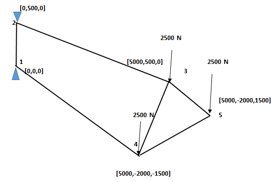
Determine the nodal deflections, reaction forces, and stress for the truss system shown below (E = 200GPa, Pipe diameter = 30 mm, Wall thickness =2mm


Results:

Discipline: Structural
Analysis Type: Static
No of elements: 06
No of Nodes:  05


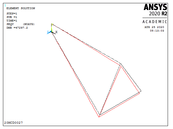
Max Deflection (Image & Table)


 PRINT REACTION SOLUTIONS PER NODE

   ***** POST1 TOTAL REACTION SOLUTION LISTING *****                       

   LOAD STEP= 1  SUBSTEP= 1                                        

   TIME= 1.0000      LOAD CASE=   0                                    


  THE FOLLOWING X,Y,Z SOLUTIONS ARE IN THE GLOBAL COORDINATE SYSTEM           


NODE      FX           FY       FZ       MX       MY       MZ   

  1   5497.1   2039.4   149.74 -0.10996E+007   0.19620E+007   0.15384E+008

  2  -5497.1   5460.6  -149.74  0.11745E+007  -0.19620E+007   0.19368E+008


 TOTAL VALUES

 VALUE  -0.75357E-005  7500.0  0.58785E-004  74871.     -0.31181 0.34751E+008


Conclusion:

The above given truss 3D truss has 05 nodes and 06 elements. In that node 1 and 2 has no degrees of freedom. Three equal loads were acting in the negative direction of y axis at nodes 3,4,5. Due to the loads the truss undergone deformation. In that maximum deformation was 47297.2mm at node 5. Element 2 has the maximum Stress value of 14560.7 N/mm2 and has maximum Strain value of 0.072804. Reaction force was acting on node 1 and node2 because of arresting the deformation. At node 1 reaction force at x, y and z axis were 5497.1, 2039.4 and 149.74 respectively and at node 2 reaction force at x, y and z axis were  -5497.1, 5460.6 and -149.74.


Comments

Popular posts from this blog

Quenching process

Quenching also called Hardening, is a heat treatment process in which steel is heated up to austenite temperature (above it's critical temperature), hold for some time and then cooled in water, oil or molten salt (rapid cooling). Due to rapid cooling, it results very hard structure - martensite (hardest form of Steel). fig.- steel component quench in oil. Due to hardening process hardness of steel increases and bitterness also increases. (brittleness increases hence hardened Steel nay not directly use). Quenching is always follow by tempering process. Due to rapid cooling in hardening process metal shape shrink, internal residual stresses are setup. That's the reason why hardening is follow by tempering.

Additive Manufacturing processes

  What is Additive Manufacturing? As the name suggests, Additive Manufacturing (also known as 3D printing) is a group of manufacturing techniques , which manufacture parts by adding successive layers of material with the help of computer control systems. Various materials that can be used in additive manufacturing (AM) are plastic, metal, concrete, also human tissue. In the additive manufacturing process, Computer-Aided Design (CAD) is created and utilized to manufacture 3-Dimension (3D) objects. Various CAD-CAM software is required to Design, Analyze, and Manufacture parts. Once CAD data is produced, Slicing software slices the design in different layers (as required by different  AM processes), and then data utilized to manufacture required material parts. Different terms like “3D printing” and “rapid prototyping” are also casually used to describe Additive manufacturing, but each one is a subset of additive manufacturing. Hence in the simple sense, Additive manufacturing technology

Mathematic modeling of polymer extrusion process

  Q-3. Briefly explain the mathematical modelling of any one of the manufacturing processes. Ans:   Mathematical model of polymer extrusion process : Polymer material consists of long chain molecules. In extrusion of thermoplastic polymers, important parameters are Material flow and type of flow Heat transfer in flow Residence time Mixing of particles in flow in multiple polymers, etc. To analyse these parameters, mathematical models are useful. Using governing equations and boundary conditions (B.C), a model is created and a solution is obtained for particular B.C. Governing equations:   To model any flow and thermal transport in the manufacturing process, conservation of mass, conservation of  energy and the force momentum balance equation is used. The equations are as follow, Where, ρ is density,  t is time, T is temperature, V is the velocity vector, μ is dynamic viscosity, F is body force, p is pressure, Cp is specific heat at constant pressure, β is coefficient of volumetric ther