
Type of ignition systems in IC Engine

The ignition system is the most important part of the SI engine (Spark Ignition Engine). The ignition system an important system used in the Internal Combustion engine. Ignition system used to ignite air-fuel mixture at the proper time and in a well suitable manner with the wild range of engine speed.

Battery Coil Ignition System

  • The essential component of the battery ignition system is,
    • Battery 
    • Ignition switch
    • Distaibıde
    • Ignition coil with ballast resistor
    • Spark plus
  • The ignition switch provided connects and disconnects the ignition system from the berry so, the engine can be started or stopped.
  • When the ignition catch is on, the contact breaker points are closed, then the current to flow from the battery through the primary winding of the ignition back to the battery through earthing.
  • It developer o magnetic field across the primary winding of the ignition and inducer back which oppose the battery current.
  • A voltage is always induced in the secondary winding load but emf is too low to produce a spark. 
  • The resulting induced current still flows in the same direction as the battery current and it charges the condenser.
  • The flow of current is reversed when the battery voltage becomes less than the voltage across the condenser plates.

FIG: Battery Coil Ignition System


Magneto Ignition System

  • The principle of working of this system is similar to the battery coil ignition system, except that the magnetic field is primary and secondary winding introduced by rotating permanent magnet.
  • Magnet revolves around a rapid change of magnetic flux.
  • Magneto flux varies from a positive to maximum -ve and back up the rapid vibration of the magnetic field induced.
  • This rate of change of flux is not rapid enough to induce high voltage for sparking. Hence, the broker points condenser is provided into the circuit.

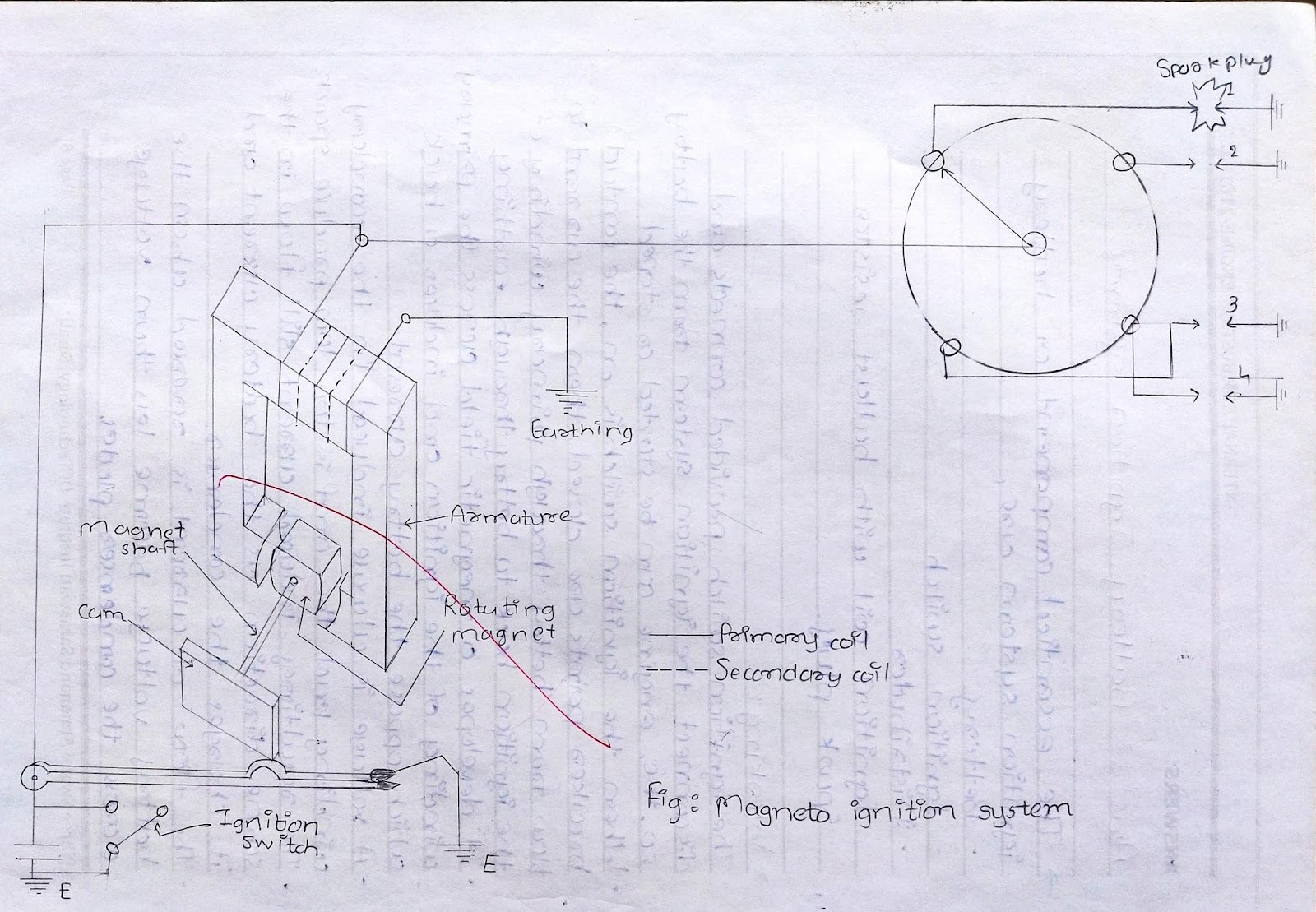
FIG: Magneto Ignition System


Comments

Popular posts from this blog

Quenching process

Quenching also called Hardening, is a heat treatment process in which steel is heated up to austenite temperature (above it's critical temperature), hold for some time and then cooled in water, oil or molten salt (rapid cooling). Due to rapid cooling, it results very hard structure - martensite (hardest form of Steel). fig.- steel component quench in oil. Due to hardening process hardness of steel increases and bitterness also increases. (brittleness increases hence hardened Steel nay not directly use). Quenching is always follow by tempering process. Due to rapid cooling in hardening process metal shape shrink, internal residual stresses are setup. That's the reason why hardening is follow by tempering.

Additive Manufacturing processes

  What is Additive Manufacturing? As the name suggests, Additive Manufacturing (also known as 3D printing) is a group of manufacturing techniques , which manufacture parts by adding successive layers of material with the help of computer control systems. Various materials that can be used in additive manufacturing (AM) are plastic, metal, concrete, also human tissue. In the additive manufacturing process, Computer-Aided Design (CAD) is created and utilized to manufacture 3-Dimension (3D) objects. Various CAD-CAM software is required to Design, Analyze, and Manufacture parts. Once CAD data is produced, Slicing software slices the design in different layers (as required by different  AM processes), and then data utilized to manufacture required material parts. Different terms like “3D printing” and “rapid prototyping” are also casually used to describe Additive manufacturing, but each one is a subset of additive manufacturing. Hence in the simple sense, Additive manufacturing technology

Mathematic modeling of polymer extrusion process

  Q-3. Briefly explain the mathematical modelling of any one of the manufacturing processes. Ans:   Mathematical model of polymer extrusion process : Polymer material consists of long chain molecules. In extrusion of thermoplastic polymers, important parameters are Material flow and type of flow Heat transfer in flow Residence time Mixing of particles in flow in multiple polymers, etc. To analyse these parameters, mathematical models are useful. Using governing equations and boundary conditions (B.C), a model is created and a solution is obtained for particular B.C. Governing equations:   To model any flow and thermal transport in the manufacturing process, conservation of mass, conservation of  energy and the force momentum balance equation is used. The equations are as follow, Where, ρ is density,  t is time, T is temperature, V is the velocity vector, μ is dynamic viscosity, F is body force, p is pressure, Cp is specific heat at constant pressure, β is coefficient of volumetric ther