
Beam problems (part1- simply supported beam with UDL and point load)

 Beam problem

Problem1 Description:

A simply supported Beam of 4000 mm length as shown in fig. A point load of 500 N and UDL load of 0.4 N/mm will be applied to a solid steel beam with a rectangular cross section. The cross section of the beam is 200mm*300mm while the modulus of elasticity of the steel is 200GPa and Poisson’s ratio is 0.3. Find the maximum deflection, Shear forces, Bending moment, and Reaction forces.

problem figure

Results:

Discipline: Structural

Analysis Type: Static

Element type: Beam, 2 node 188

Material model: Linear elastic isotropic.

Section: common section of beam – rectangular c/s, B= 200, H=300.

Key points: 4 key points are taken at x= 0, 2000, 3000, 4000. (*all dimensions are in mm)

Meshing: for all 3 elements, the number of element divisions are taken as 30. 

Displacement: at key-point1 (x=0), due to hinged support constraints are chosen in translation in all directions and rotation in x and y direction. Because the beam can only rotate in z direction.

Load: at key-point 2 (x=2000), -500N point load is applied in y direction, and between key-point 1 (x=0) and key-point 3 (x=3000) UDL is taken of magnitude 0.4 N/mm. 

Max deflection and Nodal displacement:


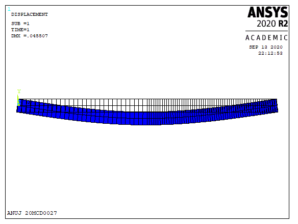
  • As per result, we get max displacement of 0.045507 mm. as per nodal displacement graph, displacement is max near the middle section of the beam.

Shear force:


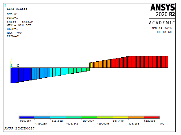
  • After selecting SMIS6 and SMIS19 in line element result, we get shear force result.

  • As per graph, we get maximum shear force of 700N (+ve y-direction) at key-point4 and minimum shear force of -986.668N (-ve y-direction) at key-point 1.

  • Between key-point 1 and 3, due to uniformly distributed load (0° curve), we get a line in SFD (1° curve).

  • At key-point 2, due to point load, SFD changes its direction. 

Bending moment:


  • After selecting SMIS3 and SMIS16 in line element result, we get a bending force result.

  • In result, maximum bending force of 0.119E+07 N.mm occurs at element 31 (near to mid span) and minimum bending force of 11666.7 N.mm occurs at element 90.

  • Here between key-point 1 and 3, due to uniformly distributed load (0° curve) we get curvature (2° curve -parabola) in BMD and in the remaining part, the curve is line.

  • After performing practical, it can be observed from fig that SFD is 1° higher than load diagram and BMD is 1° higher than SFD.


Reaction forces:


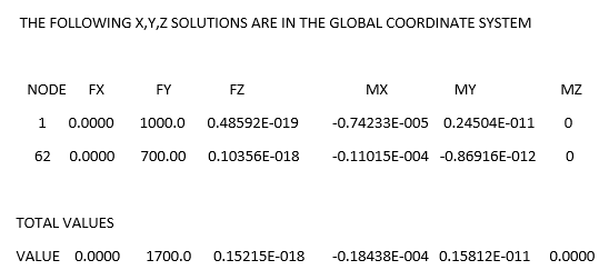
  • There is load in Y-direction only, hence reaction force in x and z direction are zero. In y direction, 

    • at node 1, reaction force = 1000 N 

    • at node 62, reaction force = 700 N, both reactions are in +ve y direction.

  • Due to the simply supported joint at both ends of the beam (at node 1 and node 62), there is no moment in the z-axis direction (2D case). But at node 1 and 62, in x and y direction, moments are present to restrict deformation. 


Comments

Popular posts from this blog

Quenching process

Quenching also called Hardening, is a heat treatment process in which steel is heated up to austenite temperature (above it's critical temperature), hold for some time and then cooled in water, oil or molten salt (rapid cooling). Due to rapid cooling, it results very hard structure - martensite (hardest form of Steel). fig.- steel component quench in oil. Due to hardening process hardness of steel increases and bitterness also increases. (brittleness increases hence hardened Steel nay not directly use). Quenching is always follow by tempering process. Due to rapid cooling in hardening process metal shape shrink, internal residual stresses are setup. That's the reason why hardening is follow by tempering.

Additive Manufacturing processes

  What is Additive Manufacturing? As the name suggests, Additive Manufacturing (also known as 3D printing) is a group of manufacturing techniques , which manufacture parts by adding successive layers of material with the help of computer control systems. Various materials that can be used in additive manufacturing (AM) are plastic, metal, concrete, also human tissue. In the additive manufacturing process, Computer-Aided Design (CAD) is created and utilized to manufacture 3-Dimension (3D) objects. Various CAD-CAM software is required to Design, Analyze, and Manufacture parts. Once CAD data is produced, Slicing software slices the design in different layers (as required by different  AM processes), and then data utilized to manufacture required material parts. Different terms like “3D printing” and “rapid prototyping” are also casually used to describe Additive manufacturing, but each one is a subset of additive manufacturing. Hence in the simple sense, Additive manufacturing technology

Mathematic modeling of polymer extrusion process

  Q-3. Briefly explain the mathematical modelling of any one of the manufacturing processes. Ans:   Mathematical model of polymer extrusion process : Polymer material consists of long chain molecules. In extrusion of thermoplastic polymers, important parameters are Material flow and type of flow Heat transfer in flow Residence time Mixing of particles in flow in multiple polymers, etc. To analyse these parameters, mathematical models are useful. Using governing equations and boundary conditions (B.C), a model is created and a solution is obtained for particular B.C. Governing equations:   To model any flow and thermal transport in the manufacturing process, conservation of mass, conservation of  energy and the force momentum balance equation is used. The equations are as follow, Where, ρ is density,  t is time, T is temperature, V is the velocity vector, μ is dynamic viscosity, F is body force, p is pressure, Cp is specific heat at constant pressure, β is coefficient of volumetric ther